

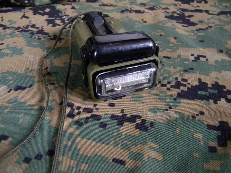
The ACR MS-2000(M), often written MS2000M, is a military distress marker with a xenon flash tube, two AA batteries and permanently attached infrared and blue filters. The basic 3990 version has stock number 6230-01-411-8535. It provides an optical marker for search and recovery forces. Depending on the filter, the flash is openly visible, detectable only with suitable night vision, or restricted to a narrower angle.
Flash source and filters remain on one light
The black main body contains the electronics, flash tube and batteries. Around it is an olive-drab sliding flashguard: a protective sleeve carrying the shield and filters. The IR filter can be placed over the clear light window or folded aside. Extending the sleeve brings the blue filter into its operating position. All three modes are therefore selected on the same light.
In the 2012 configuration, the case, clear lens and flashguard are high-impact polycarbonate, while the IR filter is butyrate. The light measures 11.4 × 5.6 × 2.8 centimetres and weighs 104 grams without batteries. A lanyard secures it to the person or worn equipment. At the lower end, a retained battery door with an O-ring seals the two battery wells.
How two small batteries produce a strong individual flash
The electronics raise battery voltage to the level required by the xenon flash tube and control its repeated firing. The MS2000M produces 50 ± 10 flashes per minute, approximately one to one and a half seconds apart.
A large side slider operates a magnetic reed switch inside the light. The slider moves the external actuator while the electrical contact remains within the sealed assembly. Switching on requires moving the slider fully to its upper stop. The tube starts flashing within a few seconds. Moving it fully down switches it off. Filter position is independent of this action: the same flash is emitted as white light, infrared or through the directional blue filter.
Three positions create different observation paths
Prepare the position with the light switched off. The flashguard must move fully, and the IR filter must lock in the selected position. A partly closed filter can allow visible light to escape sideways or obstruct the desired emission. Operation of the 2009/2012 MS-2000(M) distinguishes these positions:
| Light | Mechanical setting | Effect |
|---|---|---|
| White | Keep the flashguard retracted. Slightly lift the IR filter, rotate it 90 degrees left or right and press it into its side storage position. | The clear flash window is exposed; white light is emitted omnidirectionally. |
| Infrared | Keep the flashguard retracted. Place the IR filter over the clear light window and press down to lock it. | The filter suppresses visible light. Compatible night vision can still detect the IR flash from around the light. |
| Blue | First keep the flashguard retracted. Slightly lift the IR filter, rotate it 90 degrees aside and lock it there. Hold the main body, pull the flashguard up to its stop or engagement point, then release it. | The blue filter enters its operating position; the extended shield limits the light path to one direction. |
White light suits a deliberately conspicuous location marker. In the blue setting, the open emission direction must instead face the observer. The sleeve reduces side emission, making light orientation more significant. A correctly switched-on blue marker pointing away from an aircraft may remain unseen by its crew. The blue filter also distinguishes the light from ground fire. It does not generate a personal recognition code.
The IR filter changes the emitted spectrum without turning the omnidirectional flash into a narrow beam. The observer needs suitable night-vision equipment, and an enemy with compatible equipment can detect the same emission. Blue is effective only along the open direction of the extended sleeve. White provides the most conspicuous all-round marker. In every mode, the light window needs a clear line of sight to the expected observer.
Check filter function before relying on its effect on visibility
The 2012 configuration has a felt liner in its protective sleeve to prevent visible leakage in the IR setting. Filter surface, lock, sleeve and main case have to work together. Testing involves closing the IR filter, switching on and looking for visible flashes through the sides of the case or sleeve, then switching off. Sideways white leakage makes this light unsuitable for use requiring suppression of visible light.
A cracked or discoloured lens, damaged filters, substantial abrasion and a sticking slider are observable faults. The small black filter alone does not confirm infrared function. The older MS2000M also has no vibration indication that it is active. Without compatible night vision, the person cannot directly see the desired IR flash. A prior flash-function check and a visible-leakage check consequently answer different questions.
Batteries, endurance and a sealed battery compartment
The operating arrangement uses two 1.5-volt AA cells. The 2012 configuration uses alkaline or AA lithium batteries, with lithium specified for extreme cold or long storage. Both installed cells must match in type, brand and age. Combining a fresh cell with a heavily depleted one means the wearer cannot expect the endurance of a fresh pair. Raised polarity indicators help establish the correct insertion direction even in poor visibility.
Dirt in a battery well, damaged cells and corroded contacts affect the power supply; a dirty or damaged O-ring compromises sealing. The 2012 basic configuration has a nominal minimum strobe endurance of eight hours. That figure assumes a suitable fresh pair of cells and says nothing about the remaining capacity of batteries already used.
Flash rate can be checked, but does not measure all performance
For periodic function testing, the light can run for two minutes in its white setting, with flashes counted during the second minute. The acceptable count is 40 to 60. Initial acceptance of new lights instead counts the tenth minute after nine minutes of operation. These tests belong in a controlled environment: prolonged visible testing during a contact situation would itself become location marking. Normal test temperature is approximately 21 °C; cold can reduce flash rate.
If the rate falls outside 40 to 60 flashes per minute, examine both batteries and the contacts. Where matching replacement batteries are available, replace the pair; loose dirt can be removed with a small brush while the open wells face down. Repeat the flash-rate test afterwards. A persistent fault means the light is defective. Its sealed electronics case cannot be dismantled without destroying its integrity. A correct flash count demonstrates repeated operation, but measures neither light intensity nor IR-filter sealing or reception by the other party.
Basic model, Waterbug, Doublefly and the later M2
The exact model determines additional functions. The MS-2000(M) 3990 is the basic strobe described here. The 2012 Waterbug 3991 adds water activation. Doublefly 3994 combines the strobe with an incandescent lamp, with a nominal minimum endurance of two hours for that continuous lighting. Pressure-tested version 3989.1 reaches a 15.2-metre test depth, whereas the 2012 basic rating is ten metres. Water activation, the incandescent lamp and the greater test depth therefore cannot be assigned to a 3990 merely because its case looks similar.
The 2015 MS-2000(M2) configuration uses LEDs and adds vibration indications of activation or operating state. The basic identifier becomes 3990.2. Similar sleeve and filter arrangements thus conceal a change in light source and feedback. Longer M2 endurance figures belong to the LED version; they do not replace the eight-hour figure for the older xenon light.
From a strobe flash to actual location
In clear, dark-night visibility testing of the 2012 configuration, the light was detectable at a distance of six miles, approximately 9.6 kilometres. That observation condition explains the figure better than a distance alone. Fog, ambient light, vegetation, filters and light orientation alter the light path. A shielded blue marker also has different open observation directions from an unobstructed white flash. Filter position and clear emission direction must therefore match the visible or expected observer before a brief use.
The MS2000M transmits neither position nor identity; it places an optical reference in the terrain. An AN/PRC-112G can pass position and condition, while the light provides the final visual correlation. To prevent confusion with an unrelated or hostile light source, filter setting, timing and the agreed recognition procedure have to match.